13944849954


Products
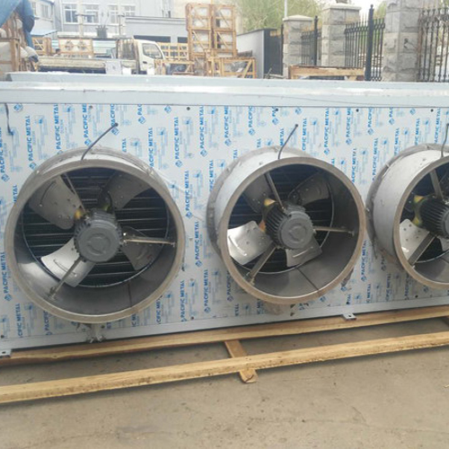
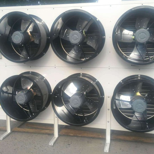
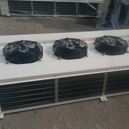
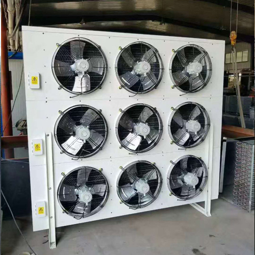
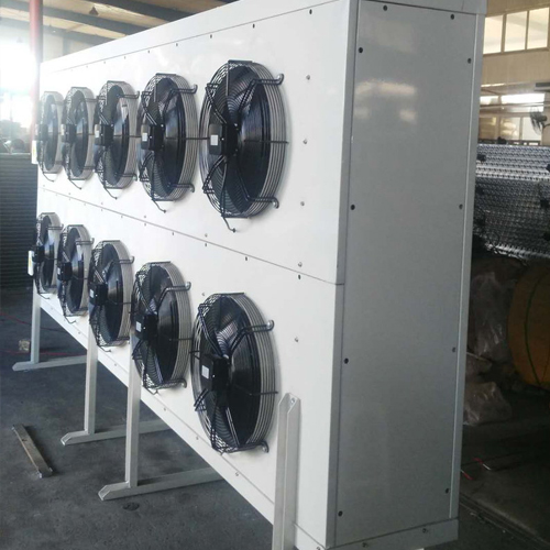
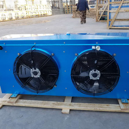
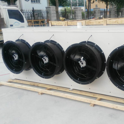
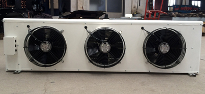
华亿游戏网(中国)安卓通用版设备-华亿游戏网(中国)安卓通用版 +华亿游戏网(中国)安卓通用版


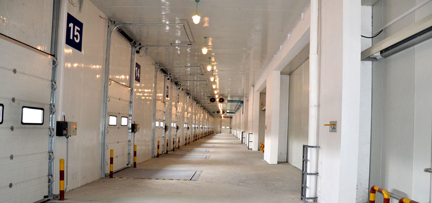
冰雪华亿游戏网(中国)安卓通用版保鲜库实例
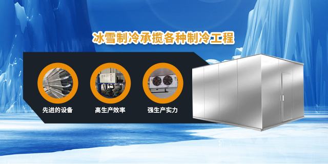
华亿游戏网(中国)安卓通用版本着"先做人,再做生意"的原则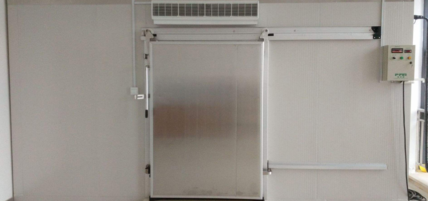
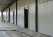
冰雪华亿游戏网(中国)安卓通用版冷藏库实例
长春冰雪华亿游戏网(中国)安卓通用版设备有限公司,长春华亿游戏网(中国)安卓通用版安装,长春专业华亿游戏网(中国)安卓通用版搭建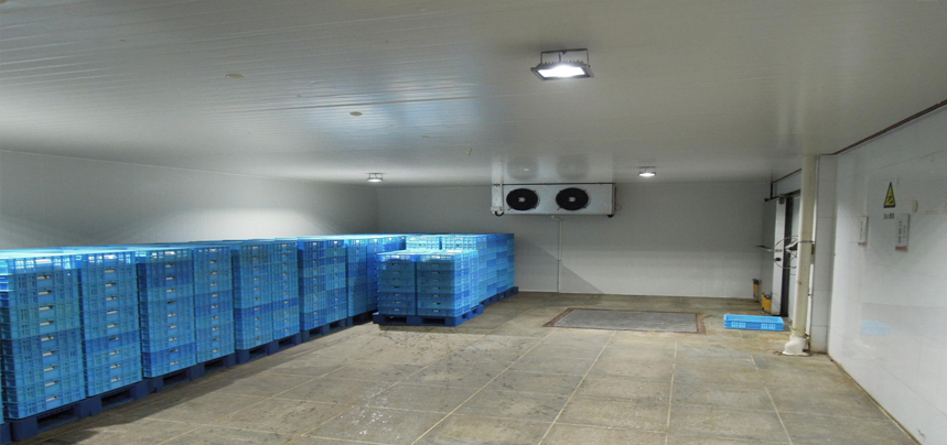
冰雪华亿游戏网(中国)安卓通用版速冻库实例
长春华亿游戏网(中国)安卓通用版设计制作,长春冷藏库,吉林省冷冻库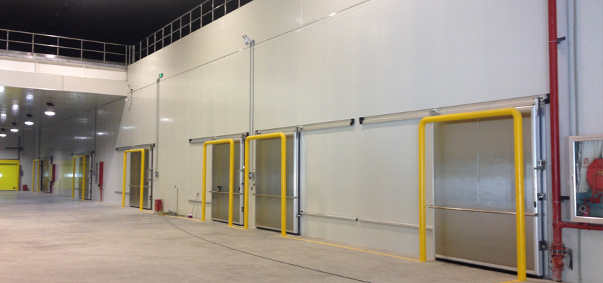
冰雪华亿游戏网(中国)安卓通用版医药华亿游戏网(中国)安卓通用版实例
吉林省大型华亿游戏网(中国)安卓通用版安装,长春蔬菜华亿游戏网(中国)安卓通用版,长春医药华亿游戏网(中国)安卓通用版,试剂华亿游戏网(中国)安卓通用版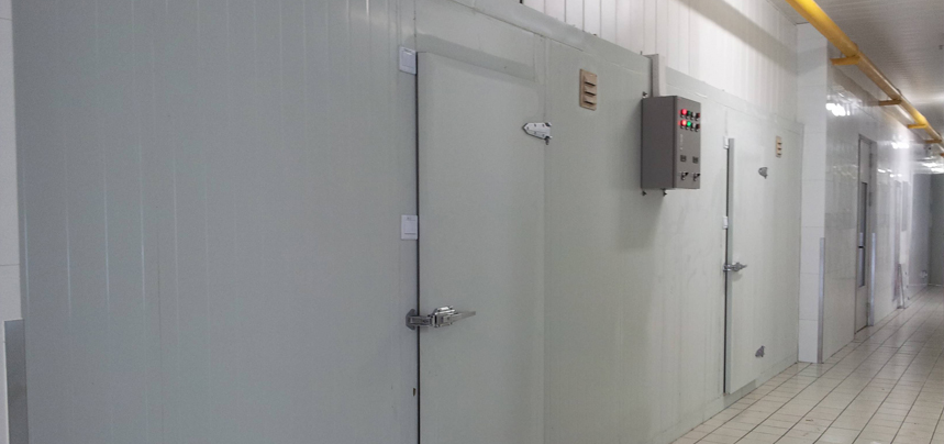
冰雪华亿游戏网(中国)安卓通用版中大型华亿游戏网(中国)安卓通用版
长春疫苗华亿游戏网(中国)安卓通用版,荫凉库,吉林省医药冷藏库,长春医药速冻库,长春拆迁华亿游戏网(中国)安卓通用版关于华亿游戏网(中国)安卓通用版

冰雪华亿游戏网(中国)安卓通用版保险库实例
经营华亿游戏网(中国)安卓通用版设备、零部件、维修工具等,可以承揽各种华亿游戏网(中国)安卓通用版工程